
Designing OR Gate using Diodes

An OR gate has two or more inputs and a single output. The definition of OR gate states that if one of the inputs is '1' the output will be '1'. The figure below shows the structure of the OR gate.


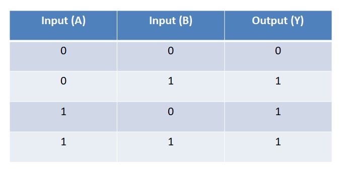
For a two-input OR gate, the relationship between input and output is shown in the truth table below.
You will notice that if any-one of the input is 1 then the output is 1.


Now let us try to understand how you can build OR gate using diodes. But first, you must understand the basic principle on which the diode works.
Look at the figure of the diode below. If you apply some positive voltage V(in) which is greater than Vth (Breakdown voltage of diode) at point A then the diode will act as a closed switch or it will be forward biased. Thus the diode will start conducting. On the other hand if you apply some negative voltage V(in) which is less than Vth, the diode will not conduct and will act as an open switch. This is called reverse biased.
Having understood the working of the diode, let us now take a look at the circuit diagram of the OR gate.


Construction:- V1 and V2 are input voltages. R2 and R3 are the source resistances. R2 and R3 are equal and R1 >> R2, R3. D1 and D2 are the diodes. R1 is a pull-down resistor. Vout is the output voltage.

Working:-
Case 1:- V1 = 0, V2 = 0
If we apply zero voltage at both V1 and V2 then the diodes will not conduct (as V1, V2 <  Vth). Therefore, the output voltage will also be zero volts.

Case 2:- V1 = 0, V2 = 5 V
In this case diode D1 will be in reverse biased (V1 < Vth) mode whereas D2 (V2 > Vth) will be forward biased and will start to conduct. thus the output voltage will be HIGH. It will not be exactly equal to the input voltage but slightly less than the input voltage. This is because of the voltage drop across R3, D2, and R1.

Case 3:- V1 = 5 V, V2 = 0 V
This is similar to case 2. The only difference is instead of D2, D1 will start conducting and the output will be HIGH.

Case 4:- V1 = 5 V, V2 = 5 V
In this case, both D1 and D2 will be forward biased and start conducting. What do you think will happen then? Will the 5 volts from V1 and 5 volts from V2 will add up to give an output voltage of 10 volts? Well, for your surprise the output voltage will still be 5 volts. 
Let us try to understand this in detail.
V1 = V2 = 5 volts
Thus, we can consider the terminals V1 and V2 to be short together and supply a common 5 v supply as shown in the figure below.
Now,
R1 = R2 = R (Say)


Also, R1 and R2 are parallel to each other. Thus their equivalent resistance will be R/2. The simplified circuit diagram is shown below.

This brings us back to case 2, where only one diode was conducting. Thus the output will be HIGH. Of course, in this case, the Vout will be slightly higher than the previous cases. This is because the equivalent resistance (R/2) is less than the source resistance (R) due to which there will be less voltage drop across the source resistance and the output will be slightly higher than 5 volts.

Comments

Popular posts from this blog

Iris Detection | Python | OpenCv

 Hello there! Welcome to another blog. In this blog you are going to learn to detect iris using OpenCv python. Here is the video in case you missed it. So, let's get started. We will start by importing the necessary libraries. import cv2 import numpy as np Now, let us import the face and eye classifier files and set the camera resolution as follows. eye = cv2.CascadeClassifier( 'haarcascade_eye.xml' ) face = cv2.CascadeClassifier( 'haarcascade_frontalface_alt.xml' ) Kernal = np.ones(( 3 , 3 ) , np.uint8) #Declare kernal for morphology cap = cv2.VideoCapture( 0 ) cap.set(cv2.CAP_PROP_FRAME_WIDTH , 320 ) ##Set camera resolution cap.set(cv2.CAP_PROP_FRAME_HEIGHT , 240 ) In a while loop let us capture an image frame, flip it(in case your camera captures inverted images) and convert it into a gray scale image. ret , frame = cap.read() ##Read image frame frame = cv2.flip(frame , + 1 ) ##Flip the image in case your camera

Object Distance Calculation Using Contour Area Method In Python - Opencv

Today we will discuss how you can find the distance of an object from the camera using python OpenCV. Check out the video below. Before we continue, you should know how to detect a colored object. Click this link to check out my previous blog on object detection and tracking. I hope after checking out my previous blog, you are able to write your own code to detect and track objects. We will take forward the Object detection and tracking code to find the distance of an object from the camera. So let's start. Let us first understand the principle using which we will find the distance of the object from the camera. Principle:- Area enclosed by the contours of an object decreases as the object moves farther from the camera. This simply means that, if your object is near to the camera, the object will appear bigger. Thus the pixel area occupied by the object will be very large. As you move the object farther from the camera, the object size in the image will start to d

Object Detection And Tracking using Python - Opencv

Let us discuss today how you can detect and track an object in real-time. We will be using Python language and Opencv library for this purpose. Check out the video below. If you have read my previous blogs, you can directly skip down to the contour part. As usual, we need to make a few assumptions for the proper working of this application. This background is always static i.e. there is no addition or subtraction of objects in the background scene. The background-color is always constant. It does not change with time. The object that will be used for writing/painting is of a different color than the background to give us sufficient contrast between foreground and background. We are ready to begin now. Let us start by installing necessary python libraries for our project using  pip install.  We will be needing  Numpy  and  Opencv  libraries. Now create a python project and create a new script. Import the required libraries into python script as shown below. import cv2